国内十大新闻优化提升
系列文章目录
文章目录
- 系列文章目录
- 前言
- 一、模型概览
- 1.1 Target Pose Generation 目标姿势生成
- 1.2 Inverse Kinematics 逆运动学
- 1.3 Manipulator Dynamics 机械手动力学
- 1.4 Pose Measurement 姿势测量
- 二、机械手定义
- 三、生成航点
- 四、模型设置
- 五、模拟机械手运动
- 六、将结果可视化
前言
本 Simulink 示例演示了逆运动学块如何驱动机械手沿指定轨迹运动。所需的轨迹被指定为机械手末端效应器的一系列紧密间隔姿势。轨迹生成和航点定义代表了许多机器人应用,如拾取和放置操作、根据空间加速度和速度曲线计算轨迹,甚至利用摄像头和计算机视觉模拟外部对关键帧的观察。轨迹生成后,逆运动学模块可将其转换为关节空间轨迹,然后用于模拟机械手和控制器的动态。
一、模型概览
加载模型,看看它是如何构建的
open_system('IKTrajectoryControlExample.slx');
该模型由四个主要操作组成:
-
Target Pose Generation 目标姿势生成
-
Inverse Kinematics 逆运动学
-
Manipulator Dynamics 机械手动力学
-
Pose Measurement 姿势测量
1.1 Target Pose Generation 目标姿势生成
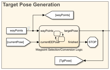
该状态流程图选择哪个航点作为操纵器的当前目标。一旦操纵器到达当前目标的容差范围内,图表就会将目标调整到下一个航点。该图表还通过 eul2tform 函数将航点的各组成部分转换并组合成一个同质变换。一旦没有更多的航点可选,图表就会终止模拟。
1.2 Inverse Kinematics 逆运动学
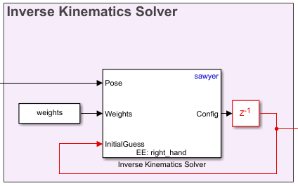
逆运动学通过计算一组关节角度,为末端效应器生成所需的姿态。使用带有刚体树模型的逆运动学,并将末端效应器的目标姿态指定为同质变换。为解决方案位置和方向的相对公差约束指定一系列权重,并给出关节位置的初始估计值。该程序块会输出一个关节位置矢量,根据程序块参数中指定的刚体树模型生成所需的姿势。为确保解决方案的平滑连续性,求解器将使用上一个配置解决方案作为起始位置。如果目标姿态在上一个模拟时间步之后没有更新,这也会减少计算的冗余。
1.3 Manipulator Dynamics 机械手动力学
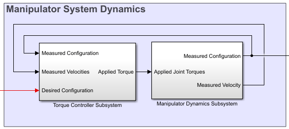
机械手动力学由两部分组成,一部分是用于产生扭矩信号的控制器,另一部分是用于模拟这些扭矩信号的机械手动力学模型。示例中的控制器使用通过机械手的反动力学计算得出的前馈组件和反馈 PD 控制器来修正误差。机械手的模型使用前向动力学模块,该模块与刚体树对象协同工作。如需更复杂的动力学和可视化技术,可考虑使用控制系统工具箱™ 块组和 Simscape Multibody™ 中的工具来替代前向动力学块。
1.4 Pose Measurement 姿势测量

姿态测量从机械手模型中获取关节角度读数,并将其转换为同质变换矩阵,作为航点选择部分的反馈信息。
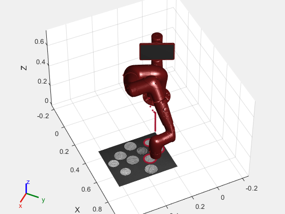
二、机械手定义
本示例使用的机械手是 Rethink Sawyer™ 机器人机械手。描述机械手的刚体树(rigidBodyTree)对象是使用 importrobot 从 URDF(统一机器人描述格式)文件导入的。
% Import the manipulator as a rigidBodyTree Object
sawyer = importrobot('sawyer.urdf');
sawyer.DataFormat = 'column';% Define end-effector body name
eeName = 'right_hand';% Define the number of joints in the manipulator
numJoints = 8;% Visualize the manipulator
show(sawyer);
xlim([-1.00 1.00])
ylim([-1.00 1.00]);
zlim([-1.02 0.98]);
view([128.88 10.45]);
三、生成航点
在本例中,操纵器的目标是追踪出在图片 coins.png 中检测到的硬币的边界。首先,对图像进行处理,找出硬币的边界。
I = imread('coins.png');
bwBoundaries = imread('coinBoundaries.png');figure
subplot(1,2,1)
imshow(I,'Border','tight')
title('Original Image')subplot(1,2,2)
imshow(bwBoundaries,'Border','tight')
title('Processed Image with Boundary Detection')
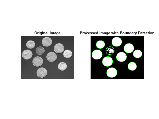
经过图像处理后,硬币的边缘被提取为像素位置。边界是一个单元格数组,每个单元格包含一个数组,描述单个检测边界的像素坐标。关于如何生成这些数据的更全面信息,请参阅示例 “图像中的边界追踪”(需要使用图像处理工具箱)。
load boundaryData.mat boundaries
whos boundaries
Name Size Bytes Class Attributesboundaries 10x1 25376 cell
要将这些数据映射到世界帧,我们需要定义图像的位置以及像素坐标和空间坐标之间的比例关系。
% Image origin coordinates
imageOrigin = [0.4,0.2,0.08];% Scale factor to convert from pixels to physical distance
scale = 0.0015;
还必须定义每个点上所需的末端效应器方向的欧拉角。
eeOrientation = [0, pi, 0];
在本例中,选择的方向是使末端效应器始终垂直于图像平面。
一旦确定了这些信息,就可以将每组所需的坐标和欧拉角编译成一个航点。每个航点都表示为一个六元素矢量,其中前三个元素对应的是操纵器在世界帧中的预期 xyz 位置。后三个元素对应于所需方位的 ZYX 欧拉角。
W a y p o i n t = [ X Y Z ϕ z ϕ y ϕ x ] \mathrm{Waypoint}=\ \!\left[X\ \ Y\ \ Z\ \ \phi_{z}\ \ \phi_{y}\ \ \phi_{x}\right] Waypoint= [X Y Z ϕz ϕy ϕx]
这些航点被连接成一个 n-by-6 的数组,其中 n 是轨迹中姿势的总数。数组中的每一行对应轨迹中的一个航点。
% Clear previous waypoints and begin building wayPoint array
clear wayPoints% Start just above image origin
waypt0 = [imageOrigin + [0 0 .2],eeOrientation];% Touch the origin of the image
waypt1 = [imageOrigin,eeOrientation];% Interpolate each element for smooth motion to the origin of the image
for i = 1:6interp = linspace(waypt0(i),waypt1(i),100);wayPoints(:,i) = interp';end
总共有 10 枚硬币。为了简化和提高速度,可以通过限制传递给航点的总数来追踪较少的硬币子集。该代码在图像中追踪的硬币数量为 3 枚。
% Define the number of coins to trace
numTraces = 3;% Assemble the waypoints for boundary tracing
for i = 1:min(numTraces, size(boundaries,1))%Select a boundary and map to physical sizesegment = boundaries{i}*scale;% Pad data for approach waypoint and lift waypoint between boundariessegment = [segment(1,:); segment(:,:); segment(end,:)];% Z-offset for moving between boundariessegment(1,3) = .02;segment(end,3) = .02;% Translate to origin of imagecartesianCoord = imageOrigin + segment;% Repeat desired orientation to match the number of waypoints being addedeulerAngles = repmat(eeOrientation,size(segment,1),1);% Append data to end of previous wayPoints wayPoints = [wayPoints;cartesianCoord, eulerAngles];
end
该数组是模型的主要输入。该数组是模型的主要输入。该数组是模型的主要输入。
四、模型设置
在模型运行之前,必须对几个参数进行初始化。
% Initialize size of q0, the robot joint configuration at t=0. This will
% later be replaced by the first waypoint.
q0 = zeros(numJoints,1);% Define a sampling rate for the simulation.
Ts = .01;% Define a [1x6] vector of relative weights on the orientation and
% position error for the inverse kinematics solver.
weights = ones(1,6);% Transform the first waypoint to a Homogenous Transform Matrix for initialization
initTargetPose = eul2tform(wayPoints(1,4:6));
initTargetPose(1:3,end) = wayPoints(1,1:3)';% Solve for q0 such that the manipulator begins at the first waypoint
ik = inverseKinematics('RigidBodyTree',sawyer);
[q0,solInfo] = ik(eeName,initTargetPose,weights,q0);
五、模拟机械手运动
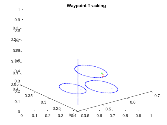
要模拟该模型,请使用 sim 命令。模型会生成输出数据集 jointData,并在两个图中显示进度:
-
X Y 图显示了机械手自上而下的追踪动作。当机械手从一个硬币轮廓过渡到下一个硬币轮廓时,圆圈之间会出现线条。
-
航点跟踪图显示的是三维进展情况。绿点表示目标位置。红点表示末端执行器通过反馈控制实现的实际末端执行器位置。
% Close currently open figures
close all% Open & simulate the model
open_system('IKTrajectoryControlExample.slx');
sim('IKTrajectoryControlExample.slx');
六、将结果可视化
模型会输出两个数据集,用于模拟后的可视化。关节配置以 jointData 的形式提供。机器人末端执行器的姿势以 poseData 的形式输出。
% Remove unnecessary meshes for faster visualization
clearMeshes(sawyer);% Data for mapping image
[m,n] = size(I);[X,Y] = meshgrid(0:m,0:n);
X = imageOrigin(1) + X*scale;
Y = imageOrigin(2) + Y*scale;Z = zeros(size(X));
Z = Z + imageOrigin(3);% Close all open figures
close all% Initialize a new figure window
figure;
set(gcf,'Visible','on');% Plot the initial robot position
show(sawyer, jointData(1,:)');
hold on% Initialize end effector plot position
p = plot3(0,0,0,'.');
warp(X,Y,Z,I');% Change view angle and axis
view(65,45)
axis([-.25 1 -.25 .75 0 0.75])% Iterate through the outputs at 10-sample intervals to visualize the results
for j = 1:10:length(jointData)% Display manipulator modelshow(sawyer,jointData(j,:)', 'Frames', 'off', 'PreservePlot', false);% Get end effector position from homoegenous transform outputpos = poseData(1:3,4,j);% Update end effector position for plotp.XData = [p.XData pos(1)];p.YData = [p.YData pos(2)];p.ZData = [p.ZData pos(3)];% Update figuredrawnow
end